
I believe that many of you have heard about PID, Temperature Control Valve (TCV), valve controller, step up controller etc. onboard vessel during your career. I know from my experience that many of the young engineers encounter problems to understand what exactly are those machinery items and how did they work.
So, in this post we will discuss about these equipment from operational point of view and I hope that after reading this post you will be able to understand what exactly are those machinery items and how did they work. I am not going to go into deep calculation formulas as this kind of theory you can find it into specialized engineering manuals or through a simple internet search.
A control loop feedback mechanism is referred to as a proportional-integral-derivative controller, or PID controller for short. The PID algorithm, as its name suggests, is comprised of three fundamental coefficients: proportional, integral, and derivative, all of which can be adjusted to achieve the best possible response.

Regarding the operation of the PID, the key concept behind this algorithm is one of “manipulating the error,” and this idea underpins the entire thing.
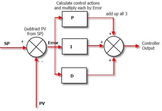
It should be obvious that the difference between the Process Variable and the Setpoint is the source of the error.
These 3 modes are used in different combinations:
-
-
- P – Sometimes used
- PI – Most often used
- PID – Sometimes used
- PD – Very rare, useful for controlling servomotors.
-
The proportional corrects individual occurrences of error, the integral corrects the accumulation of error over time, and the derivative corrects the difference between the error that is currently occurring and the error that occurred the last time it was examined.
The derivative will have the effect of reducing the overshoot that is produced as a result of P and I.
When there is a significant amount of error, the P and the I will cause the controller output to be pushed. Because of this controller’s responsiveness, the error can vary very quickly, which in turn causes the derivative to more aggressively counteract the P and the I.
The mode of how your PID controller controls the valve involved it is best described in the controller manual, and therefore you need to read the manual carefully before any intervention or tuning attempt of the controller.
Adjusting the control parameters of a control loop to their optimal values in order to get a desired response is what is meant by “tuning” a control loop. These control parameters include the gain/proportional band, integral gain/reset, and derivative gain/rate.
When the Proportional Gain (KP) is set too high, it will cause values to oscillate and will have a tendency to induce an offset. The Integral Gain, often known as KI, will work to cancel out the offset. A higher value of KI indicates that the Setpoint will approach the PV too quickly, and if this event occurs very quickly, it increases the likelihood that the process variable will be unstable. This situation is kept under control by the Derivative Gain KD.
Manual PID tuning is done by setting the reset time to its maximum value and the rate to zero and increasing the gain until the loop oscillates at a constant amplitude. (When the response to an error correction occurs quickly a larger gain can be used. If response is slow a relatively small gain is desirable). Then set the gain of the PID controller to half of that value and adjust the reset time so it corrects for any offset within an acceptable period. Finally, increase the rate of the PID loop until overshoot is minimized.
Onboard vessels the PID controllers are mostly used for Temperature Control Valves (TCV) in cooling and heating systems (water cooling, purifiers’ heaters, FO heaters and LO coolers etc.).

These valves are suited for use in vessel’s applications and process control situations in which fluids need to be mixed or redirected in order to obtain the desired temperatures. They can also be utilized in cogeneration systems to regulate temperatures within the heat recovery loop, so ensuring that the engine is cooled appropriately and making the most of the heat recovery process.
In most cases, the actuated control valve is a component of a comprehensive system that monitors changes in temperature with the assistance of an external probe.

The valve ports are either opened or closed by an external power source after receiving a signal from the probe, which is sent to a control panel.


Example of control panels
Common sorts of systems include those that are electric, pneumatic, or a combination of the two.

This kind of valve requires more components in order to function properly, but it does provide a number of advantages over other kinds. To begin, they are typically far more accurate, and because of this, they are the best choice when the application in question calls for extremely exact temperature control. Second, in contrast to thermostatic valves, these systems make it possible to make a flexible adjustment to the temperature range in the event that the working conditions shift.
As mentioned above actuated valves both work equally well for applications that require mixing fluids of two different temperatures or for diverting fluids to a cooler, heat exchanger, or radiator. They can can operate in any position, allowing you to mount the valves based on what works best with the existing pipework.
It is imperative that the temperature of the engine fluids be kept under control in order to guarantee the efficiency and performance of the equipment. Failure to maintain temperature constancy can, depending on the application, contribute to poor fuel consumption, high emission output, and smoke.
The temperature of the charge air inlet has a significant impact on the performance of the engine. For the combustion process to work properly, various grades and kinds of fuel need for varying temperatures at the air input. In addition, regulating the dew point helps cut down on corrosion and improve fuel economy.
The temperature of the jacket water can have an effect on the amount of NOx emissions, the efficiency of the engine, the amount of fuel consumed, and smoke. In this application, keeping the temperature at a high enough level is essential to load acceptance; on the other hand, keeping the temperature too low might result in cold corrosion, particularly during “slow steaming.” It is possible to recover waste heat from the HT system using technology known as smart valves, which can then be used to make the system more efficient as a whole. This is an additional benefit.
When valves are used for mixing service (e.g. Auxiliary Engine’s cooling system), Port C is the cold fluid inlet port from the cooler, Port B is the hot by-pass fluid inlet, and Port A the common outlet. Port A is the temperature sensing port and will mix the hot and cold fluids in the correct proportion to produce the desired outlet temperature leaving Port A.

When valves are used for diverting services, the inlet is Port A (temperature sensing port), with Port C being connected to the cooler, and Port B connected to the cooler by-pass line.

If you have any questions regarding above, please feel free to use our existing forum Seafarer’s World and will try to answer to all your queries. You can use the feedback button as well!
If you like my posts, please don’t forget to press Like and Share. You can also Subscribe to this blog and you will be informed every time when a new article is published. Also you can buy me a coffee by donating to this website, so I will have the fuel I need to keep producing great content! Thank you!
Source and Bibliography:
- YouTube video training credit – RealPars
- Amot
- Photo credit: Amot and chiefengineerlog.com


2 Comments