
Oil mist detectors are devices that are meant to protect large diesel engines of all applications against serious damage originating from crank-drive bearings or piston components overheating.

In case of “Visatron” oil mist detector, the atmosphere of the crankcase compartment is continuously drawn out by means of header pipes sampling system from each crankcase compartment and directed through an optical opacity measuring track.
The suction vacuum required is generated through a wear-free air jet pump in the device, fed with the compressed air (drive air), usually from engine control air system.
The sample flow, consisting of the drawn in atmosphere of the crankcase compartment, is guided through an optical channel for measuring turbidity (opacity). The sample flow is measured by absorption of infrared light.

Opacity percentage is used as the dimensional unit of the turbidity:
-
- 100 % opacity means total absorption
- 0% opacity means no absorption
Oil mist becomes explosive from a concentration of approx. 50 mg of atomized oil in 1 liter of air and up, which correspond to an opacity of approx. 40 %. To learn more about this, please follow this link.
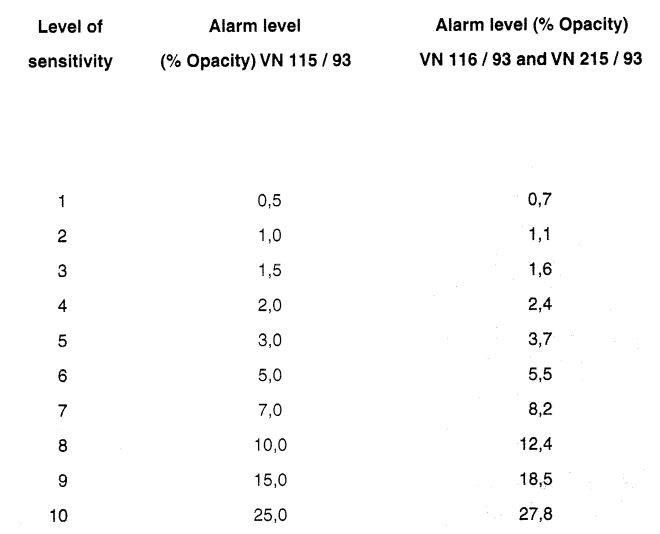
The alarm level sensitivity for different models of “Visatron” oil mist detectors are as per below table:
These devices are very reliable and require minimum maintenance from the crew side.
However, there are some periodical performance test and calibration that are required in order to ensure that the device is working as intended and to ensure the best protection for your engine.
The performance test and calibration must be done when the engine is stopped and vessel is at anchor or safely moored in port.
You must be aware that during the performance test the engine is not monitored by the oil mist detector.
The performance test is done following the below steps (here there is an example for Visatron VN 93 model):
-
- Open the control cover for the measuring head

-
- Wait until the READY-LED is switched off (approx. 10 sec)

-
- As above the following display appears.
- Blind the light beam of the measuring track with a wooden vane or a similar object.

-
- At devices VN 116/93 and VN 215/93 the damage check starts on the display damage compartment as can be seen in the above picture.
- When the alarm level is reached the TEST-LED lights up (TEST-ALARM). To set back the TEST-ALARM touch the ENTER-RESET button for more than 1 second and TEST-LED goes off.
- Close the control cover of the measuring head.
- After approx. 15 seconds the device is back in the normal operation.
A live test with test vapour can be carried out at the engine stand still when vessel is at anchor or safely moored in port.
The test is done as follow:
-
- Open the crankcase or, more convenient, disconnect one of the sampling pipes which leads to the oil mist detector.
- By using a smoke detector test spray, spray a short burst of vapour into the pipe or inside crankcase collecting funnel.
- Allow the oil mist detector to draw the vapours for minimum 20 seconds.
- Depending of the vapour density and suction time, whether an oil mist alarm is triggered or an oil mist alarm is triggered and a search run starts on the display damage compartment (VN 215/93 model).

As a maintenance, the requirements are as follow:
- Monthly maintenance: check the negative pressure in the measuring head (range 60 – 80 mm H2O).
-
- The negative (suction) pressure must be calibrated by adjusting the pressure regulator when the engine is at a standstill.
- Make sure engine room ventilation is in operation (pressure difference in engine room)
- Pour water inside the U-tube manometer utilizing the bottle from the service box. Both tubes shall be filled equally to the half of the scale of the manometer and must be on the same level when the manometer is not connected to the oil mist detector.
- Loosen nut (1) and turn setscrew (2) in clockwise direction slowly up to the stop.
-

-
-
- Open safety cover (3) at the throttle (5) and manually turn the setscrew (4) in clockwise direction slowly up to the stop.
- Make sure that compressed air is open (7 bar)
- Connect the U-tube manometer to the oil mist detector quick connection as below and it should show 0 pressure.
-

-
-
- Turn setscrew (4) in counterclockwise direction until the U-tube manometer indicates a negative pressure of 80 mm H2O
- Close safety cover
- Turn setscrew (2) in counterclockwise direction until the negative pressure is only 60 mm H2O
-

-
-
- Tight counter nut (1)
- Disconnect U-tube manometer.
-
- Quarterly maintenance:
-
- replace the sintered bronze filters in the measuring head. The filters must be replaced and not cleaned.
-

-
-
-
- clean the infrared filter glasses in the measuring head. Use only cotton buds to clean these filter glasses as there is a risk of scratching those.
-
-
- Six monthly maintenance ( only on devices equipped with optional siphon block): remove siphon block plug and blow clean with compressed air (max. 7 bar).
- Annually maintenance: replace sintered bronze filter in the pressure reducer.
If you have any questions regarding above, please feel free to use our existing forum Seafarer’s World and will try to answer to all your queries.
If you like my posts, please don’t forget to press Like and Share. You can also Subscribe to this blog and you will be informed every time when a new article is published. Also you can buy me a coffee by donating to this website, so I will have the fuel I need to keep producing great content! Thank you!
Source and Bibliography:
- Source and credit: Schaller Automation


